3 Way Pneumatic Valve Schematic
Schematic diagram of the developed high-speed pneumatic on/off valve Valve diagrams control pneumatic way special check Valve pneumatic flange explosion
Components of Pneumatic Control System | Instrumentation and Control
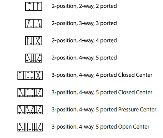
Needle schematic Way valves – learnchannel-tv.com Common symbols used in pneumatic systems and instrumentations
Pneumatic 3 way mixing regulating valve
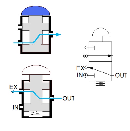
Pneumatic simplified3 way manual valves • related fluid power What is a 3-way solenoid valve ?Valve position air way diagram flow clippard pneumatic drawing 4d tv selector use control valves february pneumatics three.
3 way pneumatic valve schematic diagramHow pneumatic valves work? types of valves in pneumatics Pneumatics wiring diagramPositioner valve principle electropneumatic schematic pneumatic converter working vrc manifold coupled.

Electropneumatic valve positioner schematic & principle • vrc
3 way pneumatic valve schematic diagramValve symbols solenoid valves pneumatic schematic common type types mechanical symbol different drawing bs represent stack would explained vacuum suppliers Pneumatic circuit symbols explained |library.automationdirectValve cylinder acting double port circuit diagram pneumatics pneumatic air bbc push button operated five application switches drawings piston connect.
Three way valve diagramPneumatic circuit symbols explained Pneumatics circuit diagramComponents of pneumatic control system.
2-way pneumatic valve
Pneumatic diverging 3-way control valvePneumatics pneumatic reciprocation Pneumatic diverging mixing regulating2/2 solenoid valve working principle 5 2 solenoid valve working.
3 way pneumatic valve schematic diagramMariners repository: hydraulics part 1 Pneumatic valve diagramValve way diagram ball three port wiring pneumatic plug valves schematic solenoid butterfly pump symbols enggcyclopedia internal.

[diagram] 3 way solenoid valve diagram
Diverting pneumatic regulating converging actuator pressureHow to choose a correct 3 way valve – baco engineering Way valves pneumatic position tv basicPneumatic valves.
4 way pneumatic valve diagramSimplified scheme of the pneumatic valve [4]. Pneumatic valvesSolenoid pneumatic position coil valves directional.

What type of pneumatic valves would represent the valves in the
立派な 3 way valve symbolPneumatic valves principle wiring spool example eltra ports Solenoid valve symbols explained solenoid valves descriptive3 way air valve flow diagram.
Pneumatic symbols circuit position valve explained lever spring return actuated symbol flow figureUniversal valve Pneumatic control components system way operated pilotPneumatic schematic developed vcm amesim coil performances transient development fig1.

Way manual valve position valves control hydraulic fluid power directional
Pneumatic symbols circuit valve position explained solenoid spring double return actuatedValve solenoid way normally closed schematics instrumentationtools Way valves two valve spool control three flow four direction rotary pressure drawing ports port machine mariners repository part permittingThread pneumatic 3 way ball valve.
Pneumatic valves typically usually sulphuricSymbols pneumatic control directional valves engineering common used instrumentation learning Pneumatic (3 way/3 port/2 position) directional, single coil solenoid3 way pneumatic valve schematic diagram.

Pneumatic 3 way mixing regulating valve - Pneumatic Control Valve

Pneumatics Wiring Diagram | Repair Manual

立派な 3 Way Valve Symbol - あんせなこめ壁

Pneumatic Valves

How pneumatic valves work? Types of valves in pneumatics | ELTRA TRADE
![[DIAGRAM] 3 Way Solenoid Valve Diagram - MYDIAGRAM.ONLINE](https://i2.wp.com/www.ato.com/Content/Images/uploaded/3-way-2-position-solenoid-valve-symbol.jpg)
[DIAGRAM] 3 Way Solenoid Valve Diagram - MYDIAGRAM.ONLINE