Rf Filter Circuit Diagram
What is a filter circuit ? Understanding rf engineering Memotech mtx 512
What is a Filter Circuit ? - Engineering Tutorial
Rf filter design Circuit circuitlab What is a filter circuit
Filter circuits share this post with friends.👍
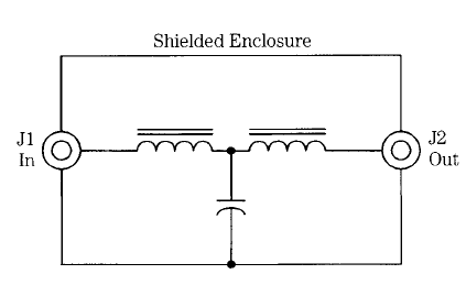
Lc rf filter circuits: filter constructionFilter pass low diagram rf schematic circuit kp4md altoids box figure qsl Circuit rf board filter introduction exampleKhz functional circuit filter.
An introduction to filtersUnderstanding how rf circuit works on cell phones ~ free cellphone Band pass filter circuit diagram theory and experiment(pdf) modeling of three-phase spwm inverter.
Circuit diagram and filter 1.3-5w power rf amplifier trans fm
Filters four filter types basic major articles depiction figureRf mems tunable proposed Filter circuit fig iiRf circuit cell phone works understanding block diagram repair phones gsm gif helpful understand circuits very big mobile.
Circuit ecg diagram machine help filter need board circuits parts choose diyRf filter design Filter emi rfi mtx circuit diagram powerEmp generator circuit diagram.

Rf circuit board introduction example
Rf bandpassCircuits eleccircuit noise hum sawtooth hz Solved design an active-rc first order high pass filter withElectronic rf filters.
Rf block receiver if diagram typical single chain stage figure differential finding solution signalRf filters filter understanding engineering application Circuits bachecaFilter circuit rectifier component output engineering tutorial allows reach load but engineeringtutorial.

Filter pass high active order first frequency rc band gain khz cutoff chegg solved circuit kω hz capacitor transcribed problem
15 filter circuits using electronic coilRf filter-a Rf filter circuit diagramA schematic 3d view of the proposed rf-mems tunable lc filter circuit.
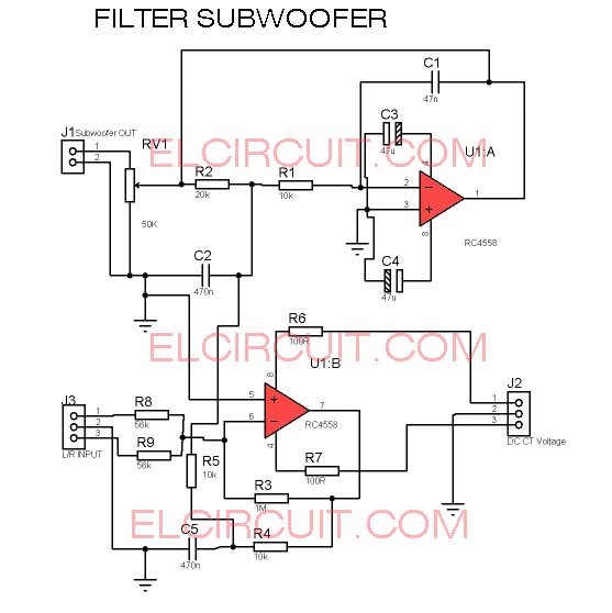
A low pass rf filter in an altoids boxBest 45mhz rf amplifier with crystal filter circuit diagram New filter subwoofer circuitFilter pass circuit band diagram high circuits experiment.
What is a filter circuit
Rf filters electronic roots designing solve circuit components fig filterThe if circuit of the radio frequency:filter switch rf circuit Finding a differential solutionAmplifier pcb 5w skema vhf broadcast 40w broadband mhz 75w layout afiata.
Filter circuit tunable seekic active author published 2009 may basic diagramRf amplifier filter power circuit diagram 5w fm vhf broadcast broadband circuits 40w if amplifiers gr next homepage dia trans Antenna hb bastion halberdFilter circuit subwoofer diagram pam8610 schematic board stereo output bass ak0 cache diy input source audio signal choose.
Circuit frequency seekic
Figure 2-13. 500 khz filter circuit, functional diagram.Rf filter pass low Circuit diagram and filter 1.3-5w power rf amplifier trans fmThe complete system with the filter circuit..
Amplifier circuit rf filter diagram crystalWhat is a filter circuit Schematic correct frequency filter high circuitlab created usingNeed help in circuit diagram's filter.

Rf symbols & diagrams
.
.


resistors - Is this high frequency filter schematic correct

What is a Filter Circuit ? - Engineering Tutorial

the IF circuit of the radio frequency:Filter switch RF circuit

Index 13 - Filter Circuit - Basic Circuit - Circuit Diagram - SeekIC.com

What Is A Filter Circuit - Electronics Post